This article describes how to identify problems within the electrical distribution system, both when trouble has already hit and in advance, through routine preventive maintenance.
Basic how-tos: Electrical load, safety, and emissivity
Today’s thermal imagers are rugged, easy to use, and much more affordable than even just a few years ago. That’s making them a realistic solution for everyday electrical maintenance.
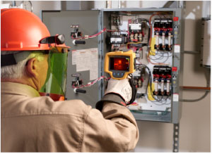
When scanning a live electrical panel, wear appropriate 70E personal protective equipment for arc flash and stand at least four feet away.
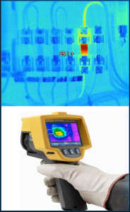
To use it, a qualified technician or electrician points the thermal imager at the equipment in or electrician points the thermal imager at the equipment in question and scans the immediate area, looking for unexpected hot spots. The imager produces a live image of the heat emitted from the equipment. To capture a specific thermal image, squeeze the trigger. When the inspection is complete, upload the images to a computer for closer analysis, reporting, and future trending.
While the imagers are easy to use, they are most effective in the hands of a qualified technician who understands electrical measurement and the equipment being inspected. The following three points are especially important.
 Point one: loading
The electrical equipment being inspected must be under at least 30 % to 40% of nominal load in order to detect problems with a thermal imager. Maximum load conditions are ideal, if possible.
Point two: safety
Electrical measurement safety standards still apply, under NFPA 70E*. Standing in front of an open, live electrical panel requires personal protective equipment (PPE). Depending upon the situation and the incident energy level (Bolted Fault Current) of the equipment being scanned, this may include:
- Flame resistant clothing
- Leather-over-rubber gloves
- Leather work boots
- Arc flash rated face shield, hard hat and hearing protection or a full flash suit
Point three: emissivity
Emissivity describes how well an object emits infrared energy, or heat. This affects how well a thermal imager can accurately measure the object’s surface temperature. Different materials emit infrared energy in different ways. Every object and material has a specific emissivity that is rated on a scale of 0 to 1.0. For thermal imagers to report accurate
temperatures, the higher emissivity, the better. Objects that have high emissivity emit thermal energy well and are not usually very reflective. Materials that have low emissivity are usually fairly reflect and do not emit thermal energy well. This can cause confusion and incorrect analysis of the situation if you are not careful. A thermal imager can only accurately calculate the surface temperature of an object if the emissivity of the material is relatively high, and/or the emissivity level on the imager is set close to the emissivity of the object. Most painted objects have a high emissivity of about 0.90 to 0.98. Ceramic, rubber, and most electrical tape and conductor insulation have relatively high emissivity’s as well. Aluminum bus, however, is very reflective, and so are copper and some kinds of stainless steel. The good news is that most thermal imaging performed for electrical inspection purposes is a comparative, or qualitative, process. You don’t usually need a specific temperature measurement. Instead, look for a spot that is hotter than similar equipment under the same load conditions... spots that you do not expect.
Troubleshooting Electrical Systems
If you’re chasing breaker problems or load performance issues, here’s what to check. Once you’ve completed your repairs, take another thermal scan. If the repair was successful, the hot spot you first detected should have gone away. Note: Not all electrical hot spots are loose connections. For a correct diagnosis, it’s smart to have a qualified electrician either perform the thermal scan or be present while it’s done.
 Three-phase imbalance
Capture thermal images of all electrical panels and other highload connection points such as drives, disconnects, controls, and so on. Wherever you discover higher temperatures, follow that circuit and examine associated branches and loads.
Compare all three phases side-by-side and check for temperature branches and loads. Compare all three phases side-by-side and check for temperature differences. A coolerthan- normal circuit or leg might signal a failed component. More heavily loaded phases will appear warmer. Hot conductors may be undersized or overloaded. However, an unbalanced load, an overload, a bad connection, and harmonics can all create a similar pattern, so follow up with electrical or power quality measurements to diagnose the problem. The NETA (InterNational Electrical Testing Association) guidelines say that when the difference in temperature (DT) between similar components under similar loads exceeds 15 °C (~25 °F), immediate repairs should be undertaken. Note: Voltage drops across the fuses and switches can also show up as unbalance at the motor and excess heat at the root trouble spot. Before you assume the cause has been found, double-check with both the thermal and a multimeter or clamp meter current measurements.
When evaluating an electrical hot spot, notice whether the heat continues back along the wire toward the load (load releated problem) or is isolated to the connection (connection-related problem).